RISC-V from scratch 3: Writing a UART driver in assembly (1 / 3)
- Introduction
- What is a UART?
- Setup
- Hardware layout in review
- Creating the basic skeleton of our driver
- Setting the base address
- Next steps
Introduction
Welcome to the third post in the RISC-V from scratch series! As a quick recap, throughout RISC-V from scratch we will explore various low-level concepts (compilation and linking, primitive runtimes, assembly, and more), typically through the lens of RISC-V and its ecosystem.
In the previous post, we used the dtc tool to inspect the layout of various hardware components in the virt QEMU virtual machine. At that point, our intention was to determine at what address the RAM lived at within that machine, but you may also recall that virt had other interesting components, one of which being an onboard UART.
In order to further expand our knowledge of RISC-V assembly, we’ll spend the next three posts writing a driver for this UART, deeply exploring important concepts such as ABIs, function prologues and epilogues, and low-level stack manipulation along the way.
If this is the first post in this series that you are tuning into and would like to follow along, do not fret! I’ll provide step-by-step instructions to get you up and running quickly.
So, without further ado, let’s begin.
What is a UART?
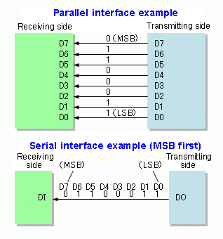
UART stands for “Universal Asynchronous Receiver-Transmitter”, and is a physical hardware device (not a protocol, à la I2C or SPI) used to transmit and receive serial data. Serial data transmission is the process of sending data sequentially, bit-by-bit. In contrast, parallel data transmission is the process of sending multiple bits all at once. This image from the serial communication Wikipedia page illustrates the difference well:
UARTs never specify a rate at which data should be received or transmitted (also called a clock rate or clock signal), which is what makes them asynchronous rather than synchronous. Instead, transmitting UARTs frame each packet of data with start and stop bits, which informs receiving UARTs of when to start and stop reading data.
You may also be familiar with USARTs (Universal Synchronous/Asynchronous Receiver-Transmitter), which are capable of acting both synchronously and asynchronously. When operating synchronously, USARTs forgo the usage of the start and stop bits and instead transmit a clock signal on a separate line that allows transmitting and receiving USARTs to sync up.
UARTs and USARTs are all around you, even if you may not realize it. They are built into nearly every modern microcontroller, our virt machine included. These devices help power the traffic lights you yield to, the refrigerator that cools your food, and the satellites that orbit the Earth for years on end.
Setup
Before we get down to writing our driver, we’ll need a few things set up to ensure we can properly compile and link. If you’ve worked through the previous two posts in this series you shouldn’t have to do anything here beyond a cd some/path/to/riscv-from-scratch.
However, if you missed the previous posts in this series:
- Follow these instructions from the first post to install the GNU RISC-V toolchain and a version of QEMU with RISC-V emulation capabilities.
- Clone or fork the riscv-from-scratch repo:
git clone git@github.com:twilco/riscv-from-scratch.git
# or `git clone https://github.com/twilco/riscv-from-scratch.git` to clone
# via HTTPS rather than SSH
# alternatively, if you are a GitHub user, you can fork this repo.
# https://help.github.com/en/articles/fork-a-repo
cd riscv-from-scratch- Check out the
pre-uart-driver-skeletonbranch which contains the code prerequisites for this post in thesrcdirectory:
git checkout pre-uart-driver-skeleton- Copy the customized linker script
riscv64-virt.ldand minimal C runtimecrt0.sto our working directory:
# note: this will overwrite any existing files you may have in `work`
cp -a src/. work
If you’re curious to know more about this customized linker script and minimal C runtime, check out the previous post.
Hardware layout in review
Before we begin writing our driver, we’ll need a little bit more information. How do we configure the UART that’s onboard virt? At what memory address can we find the receive and transmission buffers?
Let’s review the uart devicetree node using the dtc tool to try and find some of this information:
# Install 'dtc' if you don't already have it.
# I use 'brew' for MacOS - you may need to do something else.
brew install dtc
# Use qemu to dump info about the 'virt' machine in dtb (device tree blob)
# format.
# The data in this file represents hardware components of a given
# machine / device / board.
qemu-system-riscv64 -machine virt -machine dumpdtb=riscv64-virt.dtb
# Convert our .dtb into a human-readable .dts (device tree source) file.
dtc -I dtb -O dts -o riscv64-virt.dts riscv64-virt.dtb
# Search for 'uart' and display 2 lines before and 6 lines after each match.
grep uart riscv64-virt.dts -B 2 -A 6
        chosen {
                bootargs = [00];
                stdout-path = "/uart@10000000";
        };
--
        };

        uart@10000000 {
                interrupts = <0x0a>;
                interrupt-parent = <0x02>;
                clock-frequency = <0x384000>;
                reg = <0x00 0x10000000 0x00 0x100>;
                compatible = "ns16550a";
        };
At the top of our grep output, we find a node called chosen which uses the onboard UART to display any output it may produce. According to this documentation, the chosen node is special in that it doesn’t represent physical hardware. chosen is used to exchange data between firmware and a bare-metal program, such as an operating system. We won’t need to make use of chosen in this post, so let’s ignore it for now.
Next we find exactly what we’re looking for - the uart node. We see that this UART is accessible at memory address 0x10000000, indicated by the @10000000 portion of uart@10000000. We also see interrupts and interrupt-parent properties, indicating to us that this onboard UART is capable of generating interrupts.
For those unfamiliar, an interrupt is a signal to the processor emitted by hardware or software indicating an event needs immediate attention. For example, a UART may generate an interrupt when:
- New data has entered the receive buffer
- When the transmitter has finished sending all data in its buffer
- When the UART encounters a transmission error
These interrupts act as hooks so programmers can write code that responds to these events appropriately. We won’t be using any interrupts in this initial driver, so let’s skip these properties.
The next property down the list is clock-frequency = <0x384000>;. Referencing the devicetree specification, clock-frequency represents the frequency of the internal clock powering the UART (and likely the rest of the virt machine). The value is hexadecimal 0x384000, which is 3686400 in decimal format. This frequency is measured in hertz, and converting this value to megahertz results in 3.6864 MHz, or 3.6864 million clock ticks a second, which is a standard crystal oscillator frequency.
Our next property is reg = <0x00 0x10000000 0x00 0x100>;, which determines the memory location of our UART and for how long its memory extends. The #address-cells and #size-cells properties in the root node of our riscv64-virt.dts file are both set to <0x02>. This tells us it takes the addition of two <u32> cells to determine the address the reg begins at and two <u32> cells to determine the length the reg extends. Given the values present in our reg field, we know our UART registers begin at memory address 0x00 + 0x10000000 = 0x10000000 and extend 0x00 + 0x100 = 0x100 bytes. If this still is a little unclear, you can read about these properties in the devicetree specification.
This brings us to the last property in our uart node, compatible = "ns16550a";, which informs us what programming model our UART is compatible with. Operating systems use this property to determine what device drivers it can use for a peripheral. There are plentiful resources showing all the details necessary to implement a NS16550A-compatible UART, including this one which we’ll be referencing from here on out.
Creating the basic skeleton of our driver
We have all we need to begin writing our driver, so let’s begin. Start by ensuring you’re in the riscv-from-scratch/work directory we created in the setup section:
cd some/path/to/riscv-from-scratch/workNow create a file called ns16550a.s, in which we will start with a basic skeleton of the functions we want to expose for our driver. For now, we’ll limit this driver to simply reading and writing chars, or bytes, without worrying about other available capabilities of NS16550A UARTs, such as interrupts.
.global uart_put_char
.global uart_get_char

uart_get_char:
    .cfi_startproc
    .cfi_endproc

uart_put_char:
    .cfi_startproc
    .cfi_endproc

.end
We begin with the .global assembler directive to declare uart_put_char and uart_get_char as symbols accessible to other files linked with this one. All lines that begin with .s are assembler directives, meaning they provide information to the assembler rather than acting as executable code. A detailed description of all the basic GNU assembler directives can be found here.
Next, you’ll see definitions of each of these symbols, currently only containing .cfi assembler directives. These .cfi directives inform tools, such as the assembler or exception unwinder, about the structure of the frame and how to unwind it. .cfi_startproc and .cfi_endproc respectively signal the start and end of a function.
Finally we come to .end, which simply tells the assembler that this is the end of this file.
In the spirit of rapid iteration, let’s try to compile this against our custom linker script and C runtime. If you’re curious to know what all these flags are for, they are described in great detail in the previous post. For now, just know we are passing our custom linker script, riscv64-virt.ld, custom C runtime, crt0.s, and NS16550A driver, ns16550a.s, to GCC to compile, link, and assemble for us.
riscv64-unknown-elf-gcc -g -ffreestanding -O0 -Wl,--gc-sections \
    -nostartfiles -nostdlib -nodefaultlibs -Wl,-T,riscv64-virt.ld \
    crt0.s ns16550a.s
This should result in the following error:
/Users/twilco/usys/riscv/riscv64-unknown-elf-gcc-8.2.0-2019.02.0-x86_64-apple-darwin/bin/../lib/gcc/riscv64-unknown-elf/8.2.0/../../../../riscv64-unknown-elf/bin/ld: /var/folders/rg/hbr8vy7d13z9k7pdn0l_n9z51y1g13/T//ccjYQiJc.o: in function `.L0 ':
/Users/twilco/projects/riscv-from-scratch/work/crt0.s:12: undefined reference to `main'
collect2: error: ld returned 1 exit status
An utter disaster! Taking a closer look at the error, this line tells us what we need to do:
/Users/twilco/projects/riscv-from-scratch/work/crt0.s:12: undefined reference to `main`Taking a look at our crt0.s file, we do indeed see a reference to a symbol called main:
.section .init, "ax"
.global _start
_start:
    .cfi_startproc
    .cfi_undefined ra
    .option push
    .option norelax
    la gp, __global_pointer$
    .option pop
    la sp, __stack_top
    add s0, sp, zero
    jal zero, main # <~~~~~~~~~~
    .cfi_endproc
    .end
This is an easy fix - we simply need to link a file that defines the main symbol. We would’ve eventually wanted to do this anyways, as we need some way to exercise our UART driver, and we can easily do so from our main entrypoint. Create a new file called main.c in our working directory (riscv-from-scratch/work) and define a main function. We’ll also call uart_put_char to ensure that main is able to find our definition of it in ns16550a.s.
int main() {
    uart_put_char();
}
And now try running gcc again, this time including main.c:
riscv64-unknown-elf-gcc -g -ffreestanding -O0 -Wl,--gc-sections \
    -nostartfiles -nostdlib -nodefaultlibs -Wl,-T,riscv64-virt.ld \
    crt0.s ns16550a.s main.c
And this results in success! We can use nm on our newly created executable, a.out, to see all the symbols it defines, which includes the ones we just created, main, uart_get_char, and uart_put_char. Note that you may need to revisit these instructions to ensure riscv64-unknown-elf-nm is installed and available on your path or linked into your /usr/local/bin directory.
riscv64-unknown-elf-nm a.out

00000000800010a0 R __BSS_END__
000000008000109c R __DATA_BEGIN__
000000008000109c R __SDATA_BEGIN__
000000008000109c R __bss_start
000000008000189c A __global_pointer$
0000000088000000 T __stack_top
000000008000109c R _edata
00000000800010a0 R _end
0000000080000000 T _start
0000000080000018 T main
0000000080000018 T uart_get_char
0000000080000018 T uart_put_char
Setting the base address
Again referencing this resource, NS16550A UARTs have twelve registers, each accessible from some number byte offset of the base address. In order to be able to get at these registers from our driver code, we’ll first need to define a symbol representing this base address. As we discovered from the decompiled devicetree file above, riscv64-virt.dts, the base address is located at 0x00 + 0x10000000 = 0x10000000, as that is what is in the reg property:
uart@10000000 {
    interrupts = <0x0a>;
    interrupt-parent = <0x02>;
    clock-frequency = <0x384000>;
    reg = <0x00 0x10000000 0x00 0x100>;
    compatible = "ns16550a";
};
Let’s define this symbol in our linker script, riscv64-virt.ld, since this is a good place to put details specific to the virt machine:
...more above...
SECTIONS
{
  /* Read-only sections, merged into text segment: */
  PROVIDE (__executable_start = SEGMENT_START("text-segment", 0x10000));
  . = SEGMENT_START("text-segment", 0x10000) + SIZEOF_HEADERS;
  PROVIDE(__stack_top = ORIGIN(RAM) + LENGTH(RAM));
  /* >>>>>> Our newest addition. <<<<<< */
  PROVIDE(__uart_base_addr = 0x10000000);
  /* >>>>>> End of our addition. <<<<<< */
  .interp         : { *(.interp) }
...more below...
With our __uart_base_addr established and codified as a symbol, we’ll now have easy access to the NS16550A registers from within our driver file, ns16550a.s.
Next steps
Today we learned about UARTs and USARTs, the NS16550A specification, interrupts, and some additional devicetree properties. We also have created a solid skeleton for our UART assembly driver, and have codified the __uart_base_addr as a symbol in our linker file for easy UART register access.
In the next post, we’ll discuss and implement function prologues for our two driver functions uart_get_char and uart_put_char. Function prologues are an important part of making function calls possible in the world of assembly. We will be walking through a function prologue step-by-step, with diagrams detailing changes to the stack and registers with every instruction.
This post has been released - click here to check it out. If you have any questions, comments, or corrections, feel free to open up an issue or leave a comment below via utterances.
Thanks for reading!